🌐 Computer Networking
Last modified on April 07, 2022
How does the Internet work?
Internet Datagrams
Datagrams (specific kinds of packets) contain the following elements:
- To address of a node (fully specified)
- text (~1 KB)
- From address of a node (fully specified)
The Internet is a system that tries its best to deliver datagrams.
[my program] <- [someone else’s program]
Everything is built on top of the abstraction of datagrams.
Things that could happen to datagrams:
- Delivered quickly
- Delivered, corrupted text
- Delivered, tampered text
- Delivered really late
- Delivered to/from wrong address
- Never delivered
- Delivered multiple times
Key principle: Encapsulation
Packets are like nested envelopes. Abstractions exist inside the packets as “layers” that only talk to the same “layer.” Each layer cares about a header of one of the nested envelopes. E.g., TCP cares about the TCP header. Routers examine the IP header. The kernel on a machine looks at the user datagram header, e.g. to decide which port (i.e. which application) to forward the packet to.
Links to “Internet Datagrams”
- Internet Protocol (IP) (Internet Protocol (IP))
Everything in the internet is built on top of the Internet datagram abstraction. Datagrams conform to the Internet Protocol. Within datagrams, the data can conform to a specific protocol, e.g. ICMP, TCP, UDP etc. Such protocol information is usually written in kernel space – payload is determined by the application / user.
The header is usually 24 bytes (well, no one uses the
Optionsfield, so 20 bytes):
- Internet Datagram Header (Internet Protocol (IP) > Internet Datagram Header)
How data finds its way across the internet
| Data | IP address |
IP addresses
Every computer is given an address that’s 32 bits* long. This is known as its IP address.
IP addresses are a way to “multiplex” the scarce resource of the Internet – multiple machines can communicate over the Internet, because routers know how to deliver packets based on their destination address.
*Problem: only \(2^{32}\) = ~4 billion addresses in ipv4, which we have essentially run out of. Thus, ipv6 addresses were created that are 128 bits long.
E.g. the IP address 104.196.238.229 simply represents a 32-bit number, separated into each of its 4 bytes.
print('{0:b}'.format((104 << 24) + (196 << 16) + (238 << 8) + 229))
1101000110001001110111011100101
Here’s 127.0.0.1, aka localhost, in binary:
print('{0:b}'.format((127 << 24) + (0 << 16) + (0 << 8) + 1))
1111111000000000000000000000001
Routers
Routers forward packets one at a time. They look at IP addresses, and then send the packets to a router closer to the destination.
Modems
Links to “Modems”
- 🌐 Computer Networking (Evolution of the Internet > Level 1: Home Modem)
[TCP/IP] computer--\                /--router - Google (e.g.)
                    \              /
                    modem ---- modem
We have a pair of socket connected to each other. Sending each other internet datagrams directly.
Socket addresses on home computer
local: 18.241.0.5:53050
peer: 172.217.0.36:50
Socket addresses at Google:
local: 172.217.0.36:50
peer: 18.241.0.5:53050
Totally fine to reuse the same local address, as long as each socket is connected to a different peer address.
Problem:
We can see the path our packets take.
traceroute google.com
ping yuba.stanford.edu -t 10
| PING | yuba.stanford.edu | (171.64.74.58): | 56 | data | bytes | |||
| 64 | bytes | from | 171.64.74.58: | icmpseq=0 | ttl=61 | time=2.468 | ms | |
| 64 | bytes | from | 171.64.74.58: | icmpseq=1 | ttl=61 | time=2.198 | ms | |
| 64 | bytes | from | 171.64.74.58: | icmpseq=2 | ttl=61 | time=11.663 | ms | |
| 64 | bytes | from | 171.64.74.58: | icmpseq=3 | ttl=61 | time=2.891 | ms | |
| 64 | bytes | from | 171.64.74.58: | icmpseq=4 | ttl=61 | time=2.819 | ms | |
| 64 | bytes | from | 171.64.74.58: | icmpseq=5 | ttl=61 | time=13.421 | ms | |
| 64 | bytes | from | 171.64.74.58: | icmpseq=6 | ttl=61 | time=2.931 | ms | |
| 64 | bytes | from | 171.64.74.58: | icmpseq=7 | ttl=61 | time=26.903 | ms | |
| 64 | bytes | from | 171.64.74.58: | icmpseq=8 | ttl=61 | time=2.779 | ms | |
| 64 | bytes | from | 171.64.74.58: | icmpseq=9 | ttl=61 | time=33.740 | ms | |
| --- | yuba.stanford.edu | ping | statistics | --- | ||||
| 10 | packets | transmitted, | 10 | packets | received, | 0.0% | packet | loss |
| round-trip | min/avg/max/stddev | = | 2.198/10.181/33.740/10.887 | ms |
TTL: time to live – how long the packet has to reach its destination. if it expires, look at the FROM address, and tell the sender
Network Stack
4 layer model
As an example…imagine you open a webpage in Chrome. This is a high-level abstraction that gets translated down the network stack.
- Application Layer: Chrome client makes a HTTP request,
GET index.html. - Transport Layer: wraps the data in a TCP segment.
- Network Layer: wraps the data in an Internet Datagram.
- Link Layer: wraps the data in an Ethernet Frame.
Then, this Ethernet frame gets sent through the network infrastructure, hop-by-hop, to its destination.
At the destination, we receive an Ethernet frame, and the process proceeds in reverse:
- Link Layer: Ethernet frame arrives.
- Network Layer: get IP datagram out of the Ethernet frame.
- Transport Layer: get TCP segment out of the IP datagram.
- Application Layer: get HTTP request out of the TCP segment.
The modularity of the stack is quite elegant/nice: there have been innovations at each layer, that don’t affect the functionality of any of the other layers. This model is neither static nor all-encompassing: you can also insert other layers, e.g. TLS layer that encrypts the TCP byte stream! Proxies work at the HTTP level by forwarding everything through a proxy server, VPNs work at the datagram level (wrap a datagram in another datagram.)
More detailed
Web page
HTTP request / response
Reliable byte stream
Internet datagrams
Ethernet frames
Wave Packets
Reliability (from unreliability)
What the Internet provides
The Internet provides best-effort delivery of datagrams, up to ~1.5KB.
“best-effort” means the datagram might be:
- lost completely
- delivered more than once, out of order
- delivered with some bytes changed
- delivered but truncated.
What most users/applications want
Users want reliability – reliable retrieval of data, reliable action, reliable byte stream, reliable delivery of a large file, reliable remote procedure call
Reliability
A module behaves reliably when it:
- Provides some abstraction/interface
- Even in the face of underlying faults
- When it can’t do that, it signals failure
Big question: how to provide these abstractions reliably on top of an unreliable system?
We want to do idempotent operations; i.e. operations that have the same effect in the world, even if called multiple times / out of order.
TCP in a nutshell:
Byte stream 0..2 is “A B C”.
Byte stream 4..6 is “E F G”.
“The next byte of the stream I need from you is #5”.
Byte stream ended at [index].
^idempotent operations.
Internet Protocol (IP)
Everything in the internet is built on top of the Internet datagram abstraction. Datagrams conform to the Internet Protocol. Within datagrams, the data can conform to a specific protocol, e.g. ICMP, TCP, UDP etc. Such protocol information is usually written in kernel space – payload is determined by the application / user.
The header is usually 24 bytes (well, no one uses the Options field, so 20 bytes):
Internet Datagram Header
0 1 2 3
0 1 2 3 4 5 6 7 8 9 0 1 2 3 4 5 6 7 8 9 0 1 2 3 4 5 6 7 8 9 0 1
+-+-+-+-+-+-+-+-+-+-+-+-+-+-+-+-+-+-+-+-+-+-+-+-+-+-+-+-+-+-+-+-+
|Version| IHL |Type of Service| Total Length |
+-+-+-+-+-+-+-+-+-+-+-+-+-+-+-+-+-+-+-+-+-+-+-+-+-+-+-+-+-+-+-+-+
| Identification |Flags| Fragment Offset |
+-+-+-+-+-+-+-+-+-+-+-+-+-+-+-+-+-+-+-+-+-+-+-+-+-+-+-+-+-+-+-+-+
| Time to Live | Protocol | Header Checksum |
+-+-+-+-+-+-+-+-+-+-+-+-+-+-+-+-+-+-+-+-+-+-+-+-+-+-+-+-+-+-+-+-+
| Source Address |
+-+-+-+-+-+-+-+-+-+-+-+-+-+-+-+-+-+-+-+-+-+-+-+-+-+-+-+-+-+-+-+-+
| Destination Address |
+-+-+-+-+-+-+-+-+-+-+-+-+-+-+-+-+-+-+-+-+-+-+-+-+-+-+-+-+-+-+-+-+
| Options | Padding |
+-+-+-+-+-+-+-+-+-+-+-+-+-+-+-+-+-+-+-+-+-+-+-+-+-+-+-+-+-+-+-+-+
Time to Live (TTL)
Implementation of traceroute with TTL
Links to “Time to Live (TTL)”
- Internet Datagram Header (Internet Protocol (IP) > Internet Datagram Header)
- Transmission Control Protocol (TCP) (Transmission Control Protocol (TCP) > Mechanisms in TCP that can combat the bad aspects of datagrams:)
- packet corruption – checksum ensures that the original data is intact.
- packet lost – TTL ensures that packets don’t wander/cycle for too long, and a timeout triggers the packet to be resent.
- packet arrives more than once / out of order – idempotence is ensured through the way that TCP keeps track of seqnos of received data, and signals for the next sequence number using the ackno.
- packet corruption – checksum ensures that the original data is intact.
Protocol
Links to “Protocol”
- Internet Datagram Header (Internet Protocol (IP) > Internet Datagram Header)
- User Datagram Protocol (UDP) (User Datagram Protocol (UDP))
Problem: IP addresses only identify a machine. How does that machine know which application/program to deliver the packet to? We need another another layer of multiplexing, so that multiple applications on one computer can share one IP address.
This is where UDP comes in– we put something special, “User Datagram Protocol” (UDP) in the Protocol field of the datagram header – then in the UDP header, a nested header within the IP payload, a “port” that corresponds to a certain application. (TCP uses ports too!)
Applications such as Zoom which may not need the strict ordering/reliability of TCP may use UDP to create a custom protocol. E.g. Zoom uses UDP to deliver their packets.
Header Checksum
Links to “Header Checksum”
- Internet Datagram Header (Internet Protocol (IP) > Internet Datagram Header)
IP Payload
IP addresses are hierarchical.
Transmission Control Protocol (TCP)
TCP is a layer on top of Internet Datagrams, and it aims to fix the unreliability issues of the Internet by keeping track of which bytes have been received, and which bytes should be sent next.
See https://www.ietf.org/rfc/rfc793.txt for the full specification.
TCP Header
0 1 2 3
0 1 2 3 4 5 6 7 8 9 0 1 2 3 4 5 6 7 8 9 0 1 2 3 4 5 6 7 8 9 0 1
+-+-+-+-+-+-+-+-+-+-+-+-+-+-+-+-+-+-+-+-+-+-+-+-+-+-+-+-+-+-+-+-+
| Source Port | Destination Port |
+-+-+-+-+-+-+-+-+-+-+-+-+-+-+-+-+-+-+-+-+-+-+-+-+-+-+-+-+-+-+-+-+
| Sequence Number |
+-+-+-+-+-+-+-+-+-+-+-+-+-+-+-+-+-+-+-+-+-+-+-+-+-+-+-+-+-+-+-+-+
| Acknowledgment Number |
+-+-+-+-+-+-+-+-+-+-+-+-+-+-+-+-+-+-+-+-+-+-+-+-+-+-+-+-+-+-+-+-+
| Data | |U|A|P|R|S|F| |
| Offset| Reserved |R|C|S|S|Y|I| Window |
| | |G|K|H|T|N|N| |
+-+-+-+-+-+-+-+-+-+-+-+-+-+-+-+-+-+-+-+-+-+-+-+-+-+-+-+-+-+-+-+-+
| Checksum | Urgent Pointer |
+-+-+-+-+-+-+-+-+-+-+-+-+-+-+-+-+-+-+-+-+-+-+-+-+-+-+-+-+-+-+-+-+
| Options | Padding |
+-+-+-+-+-+-+-+-+-+-+-+-+-+-+-+-+-+-+-+-+-+-+-+-+-+-+-+-+-+-+-+-+
| data |
+-+-+-+-+-+-+-+-+-+-+-+-+-+-+-+-+-+-+-+-+-+-+-+-+-+-+-+-+-+-+-+-+
Sequence Number (seqno)
Links to “Sequence Number (seqno)”
- TCP Header (Transmission Control Protocol (TCP) > TCP Header)
- Transmission Control Protocol (TCP) (Transmission Control Protocol (TCP) > Mechanisms in TCP that can combat the bad aspects of datagrams:)
- packet corruption – checksum ensures that the original data is intact.
- packet lost – TTL ensures that packets don’t wander/cycle for too long, and a timeout triggers the packet to be resent.
- packet arrives more than once / out of order – idempotence is ensured through the way that TCP keeps track of seqnos of received data, and signals for the next sequence number using the ackno.
- packet corruption – checksum ensures that the original data is intact.
Acknowledgement Number (ackno)
Links to “Acknowledgement Number (ackno)”
- TCP Header (Transmission Control Protocol (TCP) > TCP Header)
- Transmission Control Protocol (TCP) (Transmission Control Protocol (TCP) > Mechanisms in TCP that can combat the bad aspects of datagrams:)
- packet corruption – checksum ensures that the original data is intact.
- packet lost – TTL ensures that packets don’t wander/cycle for too long, and a timeout triggers the packet to be resent.
- packet arrives more than once / out of order – idempotence is ensured through the way that TCP keeps track of seqnos of received data, and signals for the next sequence number using the ackno.
- packet corruption – checksum ensures that the original data is intact.
ACK
Links to “ACK”
- TCP Header (Transmission Control Protocol (TCP) > TCP Header)
- Transmission Control Protocol (TCP) (Transmission Control Protocol (TCP) > Client/server 3-way handshake: SYN, SYN/ACK, ACK)
In TCP, the two connectors to the byte stream are peers; they both can read/write from the bidirectional byte stream.
That said – there is a common pattern of usage of TCP, called the client-server model.
Client (Frankie):
TCPSocket sock;
sock.bind({"0", 3}); // this "binds" the socket to a local address: IP address and port number
sock.listen(); // "listen" for incoming connections on this socket
Server (Keith):
TCPSocket sock;
sock.connect( {"[frankie's remote IP address]", 3} ) //Connect to Frankie's IP address on port 3
This is known as the TCP 3-way handshake:
sock.connectis where the first bytes get sent – Keith sends a TCP segment with SYN flag set 1 to start the server => client stream. This initiates the connection.- Frankie responds to Keith with a SYN/ACK segment, simultaneously acknowledging Keith’s SYN bit and starting a client => server stream with the new SYN.
- Keith responds to Frankie’s SYN/ACK with another ACK (to acknowledge Frankie’s SYN.)
Note: Frankie can “accept” the connection:
TCPSocket sock_connected = sock.accept();
Note – this is not the only way a connection can be established! TCP’s rules are more general than that:
- Every stream sends: SYN, bytes, FIN
- Each byte, SYN, and FIN occupy 1 sequence number each
- Each segment that occupies a sequence number provokes an acknowledgment
This is fundamentally symmetrical: no reason why one peer has to initiate, and the other has to accept. Here’s a more symmetrical way of establishing connection:
- Peers both send SYN segments (initiating at the same time)
- Peers receive these SYN segments and send ACK segments
I.e.: If Frankie and Keith are both bound to a port number, and they both want to connect to each other at the same time, they can both call
connecton each others’ IP address + port. Callingconnectresults in a SYN flag being sent
Could consider this “4-way handshake”: SYN, SYN, ACK, ACK. 99% of connections do 3-way handshake, but this is just because of the reality that the vast majority of connections on the Internet are between client and server.
SYN
Links to “SYN”
- TCP Header (Transmission Control Protocol (TCP) > TCP Header)
- Transmission Control Protocol (TCP) (Transmission Control Protocol (TCP) > Client/server 3-way handshake: SYN, SYN/ACK, ACK)
In TCP, the two connectors to the byte stream are peers; they both can read/write from the bidirectional byte stream.
That said – there is a common pattern of usage of TCP, called the client-server model.
Client (Frankie):
TCPSocket sock;
sock.bind({"0", 3}); // this "binds" the socket to a local address: IP address and port number
sock.listen(); // "listen" for incoming connections on this socket
Server (Keith):
TCPSocket sock;
sock.connect( {"[frankie's remote IP address]", 3} ) //Connect to Frankie's IP address on port 3
This is known as the TCP 3-way handshake:
sock.connectis where the first bytes get sent – Keith sends a TCP segment with SYN flag set 1 to start the server => client stream. This initiates the connection.- Frankie responds to Keith with a SYN/ACK segment, simultaneously acknowledging Keith’s SYN bit and starting a client => server stream with the new SYN.
- Keith responds to Frankie’s SYN/ACK with another ACK (to acknowledge Frankie’s SYN.)
Note: Frankie can “accept” the connection:
TCPSocket sock_connected = sock.accept();
Note – this is not the only way a connection can be established! TCP’s rules are more general than that:
- Every stream sends: SYN, bytes, FIN
- Each byte, SYN, and FIN occupy 1 sequence number each
- Each segment that occupies a sequence number provokes an acknowledgment
This is fundamentally symmetrical: no reason why one peer has to initiate, and the other has to accept. Here’s a more symmetrical way of establishing connection:
- Peers both send SYN segments (initiating at the same time)
- Peers receive these SYN segments and send ACK segments
I.e.: If Frankie and Keith are both bound to a port number, and they both want to connect to each other at the same time, they can both call
connecton each others’ IP address + port. Callingconnectresults in a SYN flag being sent
Could consider this “4-way handshake”: SYN, SYN, ACK, ACK. 99% of connections do 3-way handshake, but this is just because of the reality that the vast majority of connections on the Internet are between client and server.
- Transmission Control Protocol (TCP) (Transmission Control Protocol (TCP) > Client/server 3-way handshake: SYN, SYN/ACK, ACK)
In TCP, the two connectors to the byte stream are peers; they both can read/write from the bidirectional byte stream.
That said – there is a common pattern of usage of TCP, called the client-server model.
Client (Frankie):
TCPSocket sock;
sock.bind({"0", 3}); // this "binds" the socket to a local address: IP address and port number
sock.listen(); // "listen" for incoming connections on this socket
Server (Keith):
TCPSocket sock;
sock.connect( {"[frankie's remote IP address]", 3} ) //Connect to Frankie's IP address on port 3
This is known as the TCP 3-way handshake:
sock.connectis where the first bytes get sent – Keith sends a TCP segment with SYN flag set 1 to start the server => client stream. This initiates the connection.- Frankie responds to Keith with a SYN/ACK segment, simultaneously acknowledging Keith’s SYN bit and starting a client => server stream with the new SYN.
- Keith responds to Frankie’s SYN/ACK with another ACK (to acknowledge Frankie’s SYN.)
Note: Frankie can “accept” the connection:
TCPSocket sock_connected = sock.accept();
Note – this is not the only way a connection can be established! TCP’s rules are more general than that:
- Every stream sends: SYN, bytes, FIN
- Each byte, SYN, and FIN occupy 1 sequence number each
- Each segment that occupies a sequence number provokes an acknowledgment
This is fundamentally symmetrical: no reason why one peer has to initiate, and the other has to accept. Here’s a more symmetrical way of establishing connection:
- Peers both send SYN segments (initiating at the same time)
- Peers receive these SYN segments and send ACK segments
I.e.: If Frankie and Keith are both bound to a port number, and they both want to connect to each other at the same time, they can both call
connecton each others’ IP address + port. Callingconnectresults in a SYN flag being sent
Could consider this “4-way handshake”: SYN, SYN, ACK, ACK. 99% of connections do 3-way handshake, but this is just because of the reality that the vast majority of connections on the Internet are between client and server.
Checksum
Links to “Checksum”
- TCP Header (Transmission Control Protocol (TCP) > TCP Header)
- Transmission Control Protocol (TCP) (Transmission Control Protocol (TCP) > Mechanisms in TCP that can combat the bad aspects of datagrams:)
- packet corruption – checksum ensures that the original data is intact.
- packet lost – TTL ensures that packets don’t wander/cycle for too long, and a timeout triggers the packet to be resent.
- packet arrives more than once / out of order – idempotence is ensured through the way that TCP keeps track of seqnos of received data, and signals for the next sequence number using the ackno.
- packet corruption – checksum ensures that the original data is intact.
Client/server 3-way handshake: SYN, SYN/ACK, ACK
In TCP, the two connectors to the byte stream are peers; they both can read/write from the bidirectional byte stream.
That said – there is a common pattern of usage of TCP, called the client-server model.
Client (Frankie):
TCPSocket sock;
sock.bind({"0", 3}); // this "binds" the socket to a local address: IP address and port number
sock.listen(); // "listen" for incoming connections on this socket
Server (Keith):
TCPSocket sock;
sock.connect( {"[frankie's remote IP address]", 3} ) //Connect to Frankie's IP address on port 3
This is known as the TCP 3-way handshake:
sock.connectis where the first bytes get sent – Keith sends a TCP segment with SYN flag set 1 to start the server => client stream. This initiates the connection.- Frankie responds to Keith with a SYN/ACK segment, simultaneously acknowledging Keith’s SYN bit and starting a client => server stream with the new SYN.
- Keith responds to Frankie’s SYN/ACK with another ACK (to acknowledge Frankie’s SYN.)
Note: Frankie can “accept” the connection:
TCPSocket sock_connected = sock.accept();
Note – this is not the only way a connection can be established! TCP’s rules are more general than that:
- Every stream sends: SYN, bytes, FIN
- Each byte, SYN, and FIN occupy 1 sequence number each
- Each segment that occupies a sequence number provokes an acknowledgment
This is fundamentally symmetrical: no reason why one peer has to initiate, and the other has to accept. Here’s a more symmetrical way of establishing connection:
- Peers both send SYN segments (initiating at the same time)
- Peers receive these SYN segments and send ACK segments
I.e.: If Frankie and Keith are both bound to a port number, and they both want to connect to each other at the same time, they can both call connect on each others’ IP address + port. Calling connect results in a SYN flag being sent
Could consider this “4-way handshake”: SYN, SYN, ACK, ACK. 99% of connections do 3-way handshake, but this is just because of the reality that the vast majority of connections on the Internet are between client and server.
Mechanisms in TCP that can combat the bad aspects of datagrams:
- packet corruption – checksum ensures that the original data is intact.
- packet lost – TTL ensures that packets don’t wander/cycle for too long, and a timeout triggers the packet to be resent.
- packet arrives more than once / out of order – idempotence is ensured through the way that TCP keeps track of seqnos of received data, and signals for the next sequence number using the ackno.
Links to “Transmission Control Protocol (TCP)”
User Datagram Protocol (UDP) (User Datagram Protocol (UDP))
Problem: IP addresses only identify a machine. How does that machine know which application/program to deliver the packet to? We need another another layer of multiplexing, so that multiple applications on one computer can share one IP address.
This is where UDP comes in– we put something special, “User Datagram Protocol” (UDP) in the Protocol field of the datagram header – then in the UDP header, a nested header within the IP payload, a “port” that corresponds to a certain application. (TCP uses ports too!)
Applications such as Zoom which may not need the strict ordering/reliability of TCP may use UDP to create a custom protocol. E.g. Zoom uses UDP to deliver their packets.
User Datagram Protocol (UDP)
Problem: IP addresses only identify a machine. How does that machine know which application/program to deliver the packet to? We need another another layer of multiplexing, so that multiple applications on one computer can share one IP address.
This is where UDP comes in– we put something special, “User Datagram Protocol” (UDP) in the Protocol field of the datagram header – then in the UDP header, a nested header within the IP payload, a “port” that corresponds to a certain application. (TCP uses ports too!)
Applications such as Zoom which may not need the strict ordering/reliability of TCP may use UDP to create a custom protocol. E.g. Zoom uses UDP to deliver their packets.
Domain Name System (DNS)
Have to ask Domain Name Servers to convert a domain name to an IP address.
Internet Datagram contains User Datagram. User Datagram contains Domain Name System lookup / response
How does DNS work from the client side?
A DNS request is a request for a hostname-to-IP address mapping. E.g., “tell me the IP address for tiktok.com.”
A client sends a DNS request to a DNS server – client has a list of DNS server addresses in `etc/resolve.conf`.
The DNS request is encapsulated in a user datagram, which is in turn encapsulated in an IP (Internet) datagram. It’s often said “DNS runs over UDP” – this means that DNS uses UDP as its transport protocol.
How do names get assigned?
DNS hierarchy has a single domain at the top of the structure: the root domain (.)
Below this are the top-level domains (TLD): .com, .edu, .gov, .mil, .org, .net, .int.
Domains under the TLDs represent individual organizations or entities, e.g. Stanford (stanford.edu.) Certain organizations have domain delegation, which means that their network admin maintains the DNS database for that domain.
How do we do DNS lookup?
Can lookup the domain name through a recursive process, descending down the DNS hierarchy.
- First, we asked the root name server for “puffer.stanford.edu.”
- The root name server said, “we don’t know anything about ”puffer.stanford.edu.“, but we do know the IP addresses of the name servers that have information about names with ”.edu“ suffixes
- The root name server said, “we don’t know anything about ”puffer.stanford.edu.“, but we do know the IP addresses of the name servers that have information about names with ”.edu“ suffixes
- Then, we asked one of those “.edu” servers for the IP address of “puffer.stanford.edu.”
- This server said, “we don’t know anything about ”puffer.stanford.edu.“, but we do know the IP addresses of the servers that have information about names with ”stanford.edu“ suffixes
- This server said, “we don’t know anything about ”puffer.stanford.edu.“, but we do know the IP addresses of the servers that have information about names with ”stanford.edu“ suffixes
- So, we asked one of those servers, and we got the IP address of “puffer.stanford.edu.”
That said – that’s probably not what your computer does. DNS lookup tables are cached at many levels (even on the computer itself.)
Who stores name => IP address mappings?
Ask the root name server for puffer.stanford.edu. DNS servers cache things.
Packet Switching
Old way of networking: circuit switching
Person 1                               Person 3
        \                             /
        [Palo Alto] --------- [Austin]
        /                             \
Person 2                               Person 4
If too many people are on the “trunk” connection, it says the line is full.
Bad: this kind of network is locking us into one paradigm – phone calls. Also, other kinds of communications (e.g. email) don’t need to use the connection for long periods of time. This is inefficient.
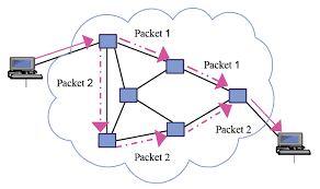
New way of networking: packet switching
Routers just handle packets. They don’t need circuits, reservations, permissions, etc. Don’t know anything about the contents of the packets – just datagrams being passed along.
| Header | Payload |
Phone calls can happen over the internet – just packets flying around. Voice ove Internet Protocol (VoIP).
Question: is there historical similarity between the phone networks and computer networks?
Packet switches have buffers
We want this infrastructure to constantly be in use. This necessitates a “queue” of packets waiting to be sent.
A
 \
  [Router]
 /
B
Serialization / Packetization delay
Propagation delay
propagation delay = link length [m] / propagation rate [m / sec] = x seconds
\(\text{delay}_{\text{progagation}} = \frac{l_i}{c}\)
Queueing delay
Links are FIFO - first-come, first-serve. Packets that aren’t ready to be sent have to wait a bit.
This is the one that can be variable – sometimes the networks are busy, and your packet has to wait in line.
\(\text{delay}_{\text{queueing}} = Q_i(t)\)
End-to-end delay
Sum the serialization + propagation + queueing delays at each link \(i\).
\(\text{delay}_{\text{end-to-end}} = \sum_i (\frac{p}{r_i} + \frac{l_i}{c} + Q_i(t))\)
Fiber Optic Cable Network
This is pretty cool.
Simple model of a router queue
Q(t): how many in queue
A(t): how many have arrived
D(t): how many have departed
Q(t) = A(t) - D(t)
Flows
Packets with certain “flows” are considered higher priority than others.
Solution: have several queues of packets. “High priority” and “low priority.”
Strict priority: always prefer high priority queue
Fair queueing: Packets are sent in the order they would complete in the bit-by-bit scheme.
Most it can be wrong: max length of packet * the rate.
Congestion Control
Capacity on the Internet is shared through “congestion control” – decentralized resource allocation.
Why do we need congestion control?
TCP provides a flow-controlled bidirectional byte stream. Each sender respects its receiver’s capacity. BUT - this doesn’t take into account the network’s capacity.
Here’s a simplified diagram of the TCP infrastructure:
              [     ]
TCP Sender => [Queue] [    Link    ] => TCP Receiver
              [     ]
From sender’s POV, 3 places packets can be:
- In the queue
- On the link
- “outstanding” – Got to the receiver, but don’t know yet (ack hasn’t come back)
The receiver’s window size caps the number of “outstanding” bytes (send but not acked, or judged lost.)
What if the receiver has a window size of 1? throughput = 1 byte / round trip time (RTT). Really slow.
What if the receiver has a larger window size? better. window keeps shifting forward as more ackno’s are received. not limited by window size, but by the link speed.
Bad scenario: slow link from sender to receiver, fast link from receiver to sender, receiver says it has a large window size. The sender will blindly send a bunch of packets, ignoring the fact that the queue will fill up.
bad because the queue fills up – it’s wasteful to send a bit that will later be dropped. (plus if the queue is full no one else can send to the link) => forcing routers to drop lots of packets, lead to congestion collapse. Lots of demand on the system, but it’s not doing useful work.
Fairness
The previous scenario also represents bad fairness – one sender hogs the queue / the useful resources. Any other connection won’t be able to send anything.
“throughput of the byte stream” = “goodput”
Different possible resource allocation strategies – no “right” one
Goal is to maximize utility.
\(\max_{\{x_r\} \in S} \sum_r U_r(x_r)\)
subject to [TODO]
If user \(r\) receives throughput \(x_r\), that produced utility \(U_r(x_r)\).
Alpha fairness utility function:
\(U(x) = \frac{x^{1- \alpha}}{1 - \alpha}\)
\(\alpha = 0\): max utilization
\(\alpha \rightarrow 1\): proportional fairness
\(\alpha = 2\): min-potential-delay fairness
\(\alpha \rightarrow \infty\): max-min fairness
Pretty powerful notion. Can use different notions of fairness simply by adjusting \(\alpha\).
Other objectives possible: flow completion time, page load time, “power” = throughput / delay…
How to control congestion? - Congestion Window (cwnd)
One way to control congestion: a second window, in addition to the receiver’s advertised window. Sender respects two windows: receiver window, and “congestion window” cwnd. So…how large should the congestion window be??
Bandwidth delay product (BDP)
Bandwidth delay product (BDP): how much data can be on the link at any moment. We don’t want to be sending bytes too fast, or too slow.
total number of bytes outstanding - bandwidth x delay product (BDP).
- Sender perspective: congestion window basically = bytes in flight (provided decent window size.)
- Network perspective: (0 bytes in queue)
- Receiver perspective: throughput / goodput (bytes that make it all the way)
Ideal behavior: with N flows, each uses cwnd of BDP / N.
How to find the right congestion window?
Ideal: Bandwidth delay product
Problem: don’t know this stuff at runtime.
How to know if congestion window is too small?
- if you can increase the window, and all good / throughput goes up.
How to know if congestion window is too big?
- if packets are lost.
Additive Increase, Multiplicative Decrease (AIMD)
start with cwnd at a small value.
on success, increase by 1 segment per RTT
on loss (i.e. when queue fills up,) assume congestion. cut cwnd in half.
Q: what is the ideal value for the router’s buffer (max queue)?
A: BDP. Cuz then the cwnd will get up to 2*BDP, and get cut down to BDP.
Follow-up Q: what if there are a million connections?
A: actually don’t need that large of a buffer.
Problem: this algorithm depends on the signal of loss to regulate itself. (In this sense, packet loss is actually a good thing. (?!)) But, the issue is, what if the sender never receives a signal of loss?
Routing
Making sure packets from one destination can get to another, along a series of “hops.”
Routers forward packets one at a time.
Routers look at IP addresses, and send the packet to a router closer to its destination.
How does a router know where to send a packet next?
The network topology is super complex. Trees can fall on power lines. Etc.
Three ways:
Flooding: every router sends an arriving packet to every neighbor.
Good thing to do if you don’t know anything about the topology: guaranteed to get to its destination (provided that the network graph is connected.)
Problem: if there are multiple paths from A to B, there can be multiple packets arriving, cycles, etc. (TTL will eventually stop it from looping, though.). Very inefficient. Packets delivered to everyone.
Source routing: end host lists the routers to visit along the way (in the packet itself.)
The packet just has a stack of routers’ IPs – each hop, pop, and send to that router.
Was used a lot in the early days of the Internet – ISPs didn’t want users to be able to source route their own packets. ISPs will block these packets.
There are contained situations where source routing makes sense, if you own the entire network.
Distributed algorithm: routers talk to each other, construct forwarding tables using a clever algorithm.
How to connect everything?
- Proto-Idea: let’s try a single minimum spanning tree.
Problems: paths get long, some links unused, need to remember to switch unused links back on
Ethernet switches build a single spanning tree between them. (Some links are switched off.)
- Better idea: Build a MST for each destination.
For each destination: a router needs to put an entry in its forwarding table to forward packets along the spanning tree rooted at that destination.
- How does it know what entry to add?
- A1: Assume links have same cost.
Basically: start from the destination node. propagate out from there, keeping track of hop count and (dest node, next hop) at each node..
Easy: just wait for the first thing to arrive.
- What if a link breaks?
Basically, each node sends out periodic updates.
- A2: Different links have different costs.
Basically: Dijkstra’s.
- Distributed Bellman-Ford Algorithm
Goal: find min-cost spanning tree to router R.
Assume routers know cost of link to each neighbor.
Router \(R_i\) maintains valueof cost \(C_i\) to reach \(R\), and the next hop.
Vector \(C = (C_1, C_2, ..)\) is the distance vector to \(R\).
Initially, set \(C = (\infty, \infty, ...)\)
- After \(T\) seconds, \(R_i\) sends \(C_i\) to neighbors
- If \(R_i\) learns of a lower cost path, update \(C_i\) + remember next hop.
- Repeat.
Problem: costs don’t always get lower. Links break, stuff’s unreliable. Algorithm is set up to ignore news like “hey, the lowest cost path just went up.”
Lol, solution: set infinity = 16. If numbers are going out of whack, we’ll see that
- run time
- algorithm converges?
- what happens when routers/links fail?
- After \(T\) seconds, \(R_i\) sends \(C_i\) to neighbors
- A1: Assume links have same cost.
Link Layer: Signals into Bits
Ethernet
Link layer sits at the bottom of the network stack - most often the link layer conforms to the Ethernet standard.
Ethernet switches
Recap: packet switch is a generic term for anything that forwards packets hop-by-hop. An Ethernet switch is a different kind of packet switch.
=> [ Lookup address ][ Update Header ] [ Queue Packet ]=>
     ^
     |
     v
   [Forwarding Table]
Links to “Ethernet switches”
- 🌐 Computer Networking (Evolution of the Internet > Level 3: Home Network)
…it allows us to connect multiple computers to a modem, given an Ethernet switch.
[TCP/IP/ computer--\                /--router - (...) -Google (e.g.)
 Ethernet]     [switch]           |
              /  |                |
      computer    \               |
                   \              /
         [Ethernet] modem ---- modem
Ethernet Switch does 4 things:
- Examine header of each arriving frame.
- If the Ethernet Destination Address (aka MAC address) is in the forwarding table, forward the frame to the correct output port(s).
- if the Ethernet Destination Address is not in the table, broadcast the frame to all ports (except the one through which the frame arrived.) i.e. flooding.
- Entries in the table are learned by checking to see if the Ethernet Source Address of arriving packets are already in the table. If not, add them.
Ethernet learns a spanning tree of the entire network.
How Internet routers handle Ethernet packets
- If the Ethernet DA of the arriving frame belongs to the router, accept the frame. else drop.
- Examine the IP version number + length of datagram.
- Decrement TTL, update IP header checksum.
- Check TTL == 0.
- If the IP DA is in the forwarding table, forward to the next hop.
- Else: If there is a Default Route entry, forward it there, otherwise drop + send ICMP message back to source.
- Find Ethernet DA for the next hop router
- Create new Ethernet frame + send.
Ethernet Frame Format
- Preamble:
- Start of Frame Delimiter:
- Destination Address:
- Type:
- Pad:
- Cyclic Redundancy Check:
The origins of Ethernet: sharing a “medium”
Ethernet is, or at least was originally, an example of multiple hosts sharing a common cable “medium”. With lots of people trying to talk, we need a protocol so things don’t get garbled. More concretely, we need to decide who gets to send, and when.
Specific protocol…
CSMA/CD Protocol
(note: historical - Ethernet doesn’t use this anymore b/c we have ethernet switches – but wireless protocols are pretty similar to this!)
When a host has a packet to transmit:
- Carrier Sense: Check if the line is quiet
- Collision detection: Detect collision as soon as possible. If a collision is detected, stop transmitting; wait a random time (but an exponentially-backing-off random time), then return to step 1.
(Real life analogy: Sometimes both people start talking at the same time, then go quiet, then both start speaking…if you stagger the re-speaking, there’s less likely to be collision.)
CSMA/CD Packet size requirement: why?
If your transmission is super short, you won’t even hear the collision while you’re still talking.
Solution: packetization time > 2 * propagation delay.
\(\frac{P}{R} > \frac{2L}{C}\)
\(P \approx 1000\)
Evolution of the Internet
Going up in complexity, here are some possible network configurations.
Level 1: Home Modem
[TCP/IP] computer--\                /--router - Google (e.g.)
                    \              /
                    modem ---- modem
We have a pair of socket connected to each other. Sending each other internet datagrams directly.
Socket addresses on home computer
local: 18.241.0.5:53050
peer: 172.217.0.36:50
Socket addresses at Google:
local: 172.217.0.36:50
peer: 18.241.0.5:53050
Totally fine to reuse the same local address, as long as each socket is connected to a different peer address.
Problem:
Level 2: Cable Modem
Now, the computers and modems talk with Ethernet – this means it’s faster, but also…
[TCP/IP/ computer--\                /--router - (...) -Google (e.g.)
Ethernet]           \              /
         [Ethernet] modem ---- modem
Benefit of Ethernet network: multiple computers can connect to the modem.
Level 3: Home Network
…it allows us to connect multiple computers to a modem, given an Ethernet switch.
[TCP/IP/ computer--\                /--router - (...) -Google (e.g.)
 Ethernet]     [switch]           |
              /  |                |
      computer    \               |
                   \              /
         [Ethernet] modem ---- modem
Level 4: Home Wireless Internet
Same thing, but the switch became wireless.
[TCP/IP/ computer--\               /--router - (...) -Google (e.g.)
 Ethernet]     [WiFI AP]          |
              /  |                |
      computer    \               |
                   \              /
         [Ethernet] modem ---- modem
Problem: as it stands, ISP has to keep track of all these different computers on their router…
Level 5: Home IPv6 Network
Solution: have a home network that hinges on a home router. Thus, rather than remembering each individual device, the ISP’s router just needs to know which part of the IP hierarchy corresponds to which home router.
[TCP/IP/ computer--\                /--router - (...) -Google (e.g.)
 Ethernet]     [Wi-Fi AP]           |
                   \                |
                   [router]         |
                     \              /
         [Ethernet] modem ---- modem
what’s the difference between a modem and a router? Modem doesn’t know anything about IP: it just translates Ethernet frames to and from electrical signals that can be sent over long distances. Router is thinking about IP, and, well, routing.
So…this is a good system, and this is basically how it works: for IPv6! But the huge problem with IPv4 is that we don’t have enough IP addresses to go around. And, as it stands, the world practically runs on IPv4. So…how can we distinguish computers in a home network, without requiring a unique IP for each device?
Level 6: TCP Proxy
Here’s one potential solution: having one single computer that acts as as a proxy for all the home devices. This proxy will make all the TCP connections for us, and it routes stuff to the individual devices using ports.
[TCP/IP/ computer--\                 /--router - (...) -Google (e.g.)
 Ethernet]     [Wi-Fi AP]            |
                   \                 |
                   [TCP proxy]       |
                    \                |
                   [router]          |
                     \              /
         [Ethernet] modem ---- modem
Problem: it’s annoying to have to manually configure every device to use that specific proxy….
Level 7: Transparent Proxy
Solution: Make TCP proxy “transparent” / “pretend” to be Google. The proxy acts as a middleman.
[TCP/IP/ computer--\                /--router - (...) -Google (e.g.)
 Ethernet]     [Wi-Fi AP]
                   \
                   [TCP proxy]
                    \
                   [router]
                     \              /
         [Ethernet] modem ---- modem
Sidenote: Oftentimes, Wi-Fi AP, TCP proxy, router, and modem all in one box.
Problem: TCP proxy is burdened with doing non-lightweight TCP stuff, like reassembling byte streams, retransmitting, etc. We wanted the proxy just for its port numbers, not for it to do all the heavy lifting! So, now, moving on to Level 8…
Network Address & Port Translation (NAT)
NA(P)T doesn’t know most of TCP (e.g. reassembling byte stream, ACKs, retransmits) – just translates addresses inside TCP segments between local <=> Google.
[TCP/IP/ computer--\                /--router - (...) -Google (e.g.)
 Ethernet]     [Wi-Fi AP]           | [DHCP]
                   \                |
                   [NAPT] [DHCP]    |
                    \               |
                   [router]         |
                     \              /
         [Ethernet] modem ---- modem
NAT mapping: (local, peer) internal <=> (local, peer) external.
When is a NAT mapping created? When the local peer initiates the connection (sends SYN.)
Why does it map when local initiates, and not remote? When SYN sent from local, it’s fine (many-to-one) but ambiguous when remote sends SYN (Since there are many local devices, and “one” remote device.)
When is a NAT mapping deleted? NAT mapping deleted when we have a TCP clean shutdown.
NATs can have wildcards: mapping a hierarchy of IP addressses to a remote.
Note: NAT is not a security feature, not a firewall etc.
Peer-to-peer Networking
What happens if we want to connect to another “peer,” just like us, rather than Google? Problem: if both users are behind a NAT, the mapping can’t be created– how does it know which computer we’re trying to connect to?
Solution 1: send everything through a TURN server (or relay or proxy) with a well-provisioned IP address.
Solution 2: one of the NATs can have a wildcard rule set up for “port forwarding” – the other computer establishes a connection.
Solution 3: NAT traversal. First, learn your IP + port from “Google.” Then, advertise that to peers. Lol. “Google” is known as a STUN server. Still need that wildcard entry (permissive NAT) on one peer.
Internet security
As of now we haven’t discussed any security in the network stack. For that, we add a new layer into the model:
Web page
HTTP request / response
Secure byte stream (TLS)
Reliable byte stream
Internet datagrams
Ethernet frames
Wave Packets
People want to have private communications, and people want to have authenticated communications.
Lots of people (especially governments) want to listen in on your traffic.
Authenticated Encryption with Associated Data - AEAD
encrypt(counter, key, plaintext) => ciphertext + tag
counter: number that never repeats
key: random 256-bit number
plaintext: any bytes
ciphertext: same length as plaintext (but gibberish)
tag: short (256-bit authenticator that proves the message is legit)
Key idea: two parties that have nothing to do with each other can agree on a random key.
Useful because we want to connect securely to “strangers” (e.g. buying something on Amazon) all the time.
Public-key encryption
Each person has a public key and a private key that are mathematically related to each other (take an encryption class.) They announce their public keys to the world, and they can send each other a message that only the other can read since they encrypt it using the peer’s public key, and the peer has the corresponding private key.
There are organizations that “certify” that a certain public key really belongs to a certain entity. Then the key gets “signed” by that authority.
Links to “🌐 Computer Networking”
Why Graphs? (Introduction > Why Graphs?)
Graphs are a general language for describing and analyzing entities with relationships/interactions. Many domains have a natural relational structure, that lends themselves to a graph representation:
- Physical roads, bridges, tunnels connecting places. 🚗
- Particles, based on their proximities. ⚛️
- Animals in a food ecosystem. 🕸
- Computer networks. 💻
- Knowledge graphs, scene graphs, code graphs…
📒 course notes
Some notes for select courses that I took in my time at Stanford.
Social Psychology
Computer Networking
CS224u: Natural Language Understanding
PSYCH 50: Cognitive Neuroscience